

 русский
 Español
 中文简体
中文简体

Straightness vs Flatness: GD&T Differences That Matter on the Shop Floor
Industry News-Every week or so, a drawing lands on our desk with two callouts that look almost interchangeable: a short straight line drawn above a shaft, and a small parallelogram drawn above a face. Straightness and flatness are both form tolerances. Neither one needs a datum reference. Both are usually checked with a dial indicator and a surface plate. And yet they ask completely different questions about a part.
Engineers who are new to GD&T often ask us which one to use. The short answer is that straightness controls a line or an axis, while flatness controls an entire surface. The longer answer is what the rest of this article is about.
Here is how we explain the two callouts to customers, and how the difference plays out on real parts.
Content
What Straightness Actually Controls
Straightness is a two-dimensional control. Applied to a flat surface, it says that each individual line element on that surface must lie between two parallel lines separated by the tolerance value. Applied to a feature of size, such as the shank of a bolt, a dowel pin or an optical shaft, it controls the derived median line, and the tolerance zone becomes a cylinder whose diameter equals the tolerance value.
Two properties make straightness unusual:
- No datum is required. The tolerance zone is free to translate and rotate until it captures the actual feature as tightly as possible, so the inspector is measuring form only, not orientation or location.
- It works in one direction at a time. A surface that measures well along its length can still be bowed, cupped or twisted across its width, and a straightness callout taken in a single direction will not catch that.
A 0.02 mm straightness callout on a shaft shank means the derived median line has to fit inside a 0.02 mm diameter cylinder over the full length of the feature. If the drawing adds the maximum material condition modifier next to the tolerance, the allowable error grows as the actual diameter departs from maximum material condition. That bonus tolerance is what lets a slightly undersized shaft bend a little more and still pass inspection.
Where straightness really earns its place is on long, slender features that slide, rotate or align something else: guide rods, spindles, ejector pins, valve stems, and shaft cores inside small gearboxes and rotary mechanisms.
What Flatness Really Means
Flatness takes the same idea and stretches it across an entire surface. The tolerance zone is two parallel planes separated by the tolerance value, and every point on the controlled surface has to sit between them. Like straightness, flatness needs no datum, and the two planes are free to tilt until they capture the surface as tightly as possible.
That freedom is the important part. A flatness callout does not care how the surface is oriented in space. It only cares that the surface itself is not bowed, dished or wavy. A perfectly flat face sitting at three degrees to the bottom of the part is still flat.
Straightness and flatness do relate to each other. A surface that is flat is automatically straight in every direction you could draw a line across it. The reverse is not true. Picture a sheet of paper rolled gently around a large cylinder. Every line running along the roll is perfectly straight, but the sheet as a whole is curved. A straightness callout would accept that sheet. A flatness callout would reject it.
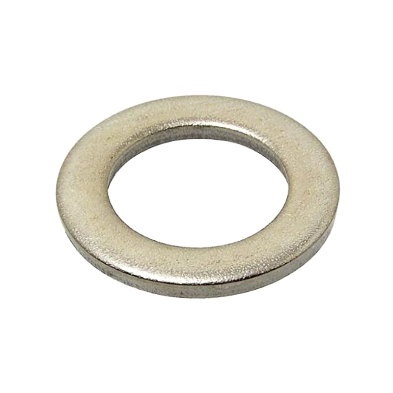
Flatness is also the more accurate description when a face has to seal, slide or sit flush against another face under load. A washer that rocks on a housing, or a valve seat that does not close evenly, is a flatness problem, not a straightness problem.
Straightness vs Flatness: The Difference in a Table
| Aspect | Straightness | Flatness |
|---|---|---|
| Tolerance zone | Two parallel lines on a surface, or one cylinder on an axis | Two parallel planes |
| Geometry controlled | One line element, or the derived median line | The entire surface, all at once |
| Datum required | No | No |
| Dimensional nature | Two dimensional, a line | Three dimensional, a surface |
| Relationship to the other | Does not imply flatness | Implies straightness in every direction |
| Typical features | Shafts, pins, rods, spindles, studs | Sealing faces, washer and nut faces, flanges, mounting pads |
| Common check | Indicator sweep along the line, V-blocks for an axis, CMM line scan | Indicator sweep on a surface plate, optical flat, CMM grid scan |
The line-versus-surface distinction produces a few practical consequences that catch people out:
- Flatness implies straightness in all directions. If a face is flat within 0.05 mm, any line drawn on it is straight within 0.05 mm as well.
- Straightness in one direction says nothing about the perpendicular direction. A part can pass a unidirectional straightness check and still rock on a surface plate.
- Axis straightness and surface straightness behave differently, even though they are called by the same name and printed with the same kind of callout.
- Neither callout controls surface texture, waviness at another scale, or the orientation of the feature to a datum. Those need surface finish notes, profile, parallelism or perpendicularity instead.
Where Each Callout Belongs on a Real Drawing
In practice, the two callouts tend to live in different corners of a print.
Straightness usually appears on
- Guide rods, spindles and plungers that must run true along their length.
- Dowels, taper pins and locating pins that set the position of a fixture or a plate.
- Shaft cores, stepped shafts and optical shafts in small rotary assemblies.
- Long studs and threaded rods where bending would misalign the joint.
Flatness usually appears on
- Sealing faces on valve bodies, fittings and hydraulic components.
- Washer faces, nut bearing faces and bolt head bearing faces that spread clamping load evenly.
- Flange faces, gear end faces, mounting pads and cover plates that bolt down and must not leak.
- Any face that slides against another face, such as a wear plate or a slide cover.
A hexagon socket head cap screw is a good example of both callouts living on the same part. The shank may carry an axis straightness callout so it does not bind in a clearance hole, while the underside of the head may carry a flatness callout so the clamping load spreads evenly instead of concentrating on one edge.
How We Measure Both on the Shop Floor
Neither tolerance is difficult to check, but both are easy to check badly.
Measuring straightness
For a line on a surface, the part sits on a surface plate and a dial indicator sweeps along the feature. The spread between the highest and lowest readings, taken along that single line, is the straightness error. For an axis, the part is supported in V-blocks or between centres, rotated, and swept along its length. The direction of the high spots matters as much as their size, because what the callout really refers to is the derived median line and not the surface you can touch.
Measuring flatness
On a surface plate, a height gauge or indicator sweeps a grid across the face, and the spread between the highest and lowest readings is the flatness error. For lapped or fine ground faces, an optical flat and a monochromatic light source show interference bands that map the shape of the surface in seconds. For complex or interrupted faces, a CMM grid scan is usually the practical route.
Whichever method is used, three things decide whether the number means anything. Support the part the way it sits in the assembly, because three-point support prevents the rocking that inflates every reading. Let the part and the gauge reach the same temperature, since a 100 mm steel face grows about 0.0012 mm for every degree Celsius. And clean the surface, because a single chip on a surface plate is easily several micrometres tall. Keeping those variables under control is most of what dimensional accuracy work is about, and we covered it in more detail in our note on how we keep dimensional accuracy under control.
Over-Tolerancing Costs More Than Under-Tolerancing
If there is one habit we push back on, it is a flatness or straightness callout copied from a previous drawing onto a part that never needed it.
Tightening flatness from 0.05 mm to 0.01 mm on a washer face does not just change a number on a spreadsheet. It changes the process. It means lapping or fine grinding, more frequent wheel dressing, extra inspection stations, sorting, and a higher scrap rate. The same is true for straightness on a shaft: a 0.01 mm axis callout on a 200 mm shank usually turns a turning operation into a grinding operation.
A few rules of thumb we use when we review a print with a customer:
- Ask what the feature actually does. Sealing, sliding and locating faces earn a flatness callout. Cosmetic faces rarely do.
- Keep the tolerance as generous as the function allows. If the assembly tolerates 0.1 mm of variation, a 0.05 mm flatness callout is already twice as strict as needed.
- Use straightness for axes and lines, flatness for areas. Mixing them up is the most common reason a part gets rejected for something that never mattered.
- Remember that flatness implies straightness. Putting both on the same face is usually redundant.
Custom work is where this conversation matters most, because every nonstandard fastener or machined part starts with a drawing and a decision about what really has to be controlled.
Straightness and flatness are not competing callouts. They describe two different shapes of error: a line that wandered, and a surface that left its plane. Once that distinction is clear, drawing decisions get easier, and inspection gets shorter, because nobody has to argue about which tolerance zone applies.
If a print on your desk looks ambiguous, or a tolerance seems stricter than the job needs, send it over. We would rather talk it through before the chips fly than sort parts afterwards.
Our Products //
Hot Products

If you are interested in our products, please consult us
Kunshan Hong Yong Sheng Precision Hardware Products Co.,Ltd. All Rights Reserved. Customised Fastener Manufacturer in China
