

 русский
 Español
 中文简体
中文简体

Facing on a Lathe: Setup, Tool Geometry, Feeds and Surface Finish Tips
Industry News-Facing is usually the first operation a new machinist learns, and it is often the one that quietly decides whether a part is good or scrap. If you have watched a tool travel straight across the end of a spinning workpiece and leave a flat, even surface behind, you have already seen facing on a lathe in action. What looks simple takes more thought than most people expect: tool height, feed direction, cutting speed and workholding all show up in the finished face.
This guide covers the practical side of facing on manual and CNC lathes, from setting up the job through troubleshooting, and finishes with the details that matter when a flat face has to hold a tolerance in production.
Content
- 1 What Facing on a Lathe Actually Does
- 2 Setting Up for a Clean Facing Cut
- 3 Facing In or Facing Out
- 4 Speeds, Feeds and Depth of Cut
- 5 Common Facing Problems and How to Fix Them
- 6 Facing on a CNC Lathe
- 7 Why the Face Often Matters More Than the Diameter
- 8 Mating Faces on Bushings and Housings
- 9 Checklist Before Your Next Facing Cut
What Facing on a Lathe Actually Does
Facing reduces the length of a workpiece and produces a flat surface perpendicular to the axis of rotation. The workpiece turns while a single-point tool feeds across the end face, usually from the outside diameter toward the center, or the other way around. That perpendicular feed is the key difference from turning, where the tool travels parallel to the axis and reduces the diameter instead.
In a working shop, facing does several jobs at once:
- Creates a clean, square datum face that later operations can be measured from.
- Squares the sawn or rough end of bar stock so the part has a known length.
- Removes the ragged edge left behind by a band saw or a parting tool.
- Prepares the end for center drilling, chamfering or threading.
Because so much depends on it, a face that is out of square, tapered or dished pushes error into every following step.
Setting Up for a Clean Facing Cut
Most facing problems are set-up problems in disguise. Before touching the feed lever, take care of a few basics.
Workholding and overhang
Grip the workpiece as close to the chuck jaws as the operation allows and keep the unsupported length short. On thin discs or rings, a light pass with a gentle feed beats a heavy cut that springs the part away from the tool. If the face is the only feature being machined, a soft jaw or a simple fixture will often do more for accuracy than any change to the cutting parameters.
Tool height on center
Set the tool tip exactly on the spindle centerline. A tool set above center leaves a small nub at the middle of the face; set below center, it rubs, pushes the work and produces a rough, work-hardened surface. A center gauge, a steel rule pinched between tool and work, or a dial indicator on the cross slide will get you close, and a light test cut confirms it.
Tool choice and geometry
Right-hand and left-hand tools feed in opposite directions, so match the tool to the direction you intend to travel and make sure the cutting edge, not the flank, engages the work. Keep tool overhang to the minimum that clears the job. Positive rake geometry suits lighter machines, a small nose radius gives a finer finish but a weaker tip, and a larger radius raises cutting forces enough to chatter on slender parts.
Facing In or Facing Out
Feed direction is a decision worth making deliberately rather than out of habit.
- Facing out (center to outside diameter): the cut starts near the middle and travels outward. The tool exits the work cleanly at the outer edge, which often improves the finish on the closing part of the face and pushes the burr to the outside diameter, where a file or chamfer removes it easily.
- Facing in (outside diameter toward center): the tool enters at the outer edge and finishes at the center. This is often preferred when a burr near the bore is easier to manage, or when a following center-drilling operation will remove that material anyway.
Many machinists rough toward the center and take the finishing pass outward. Whichever direction you choose, keep it consistent across a batch so the faces stay interchangeable.
Speeds, Feeds and Depth of Cut
One quirk of facing is that surface speed changes as the tool moves. At the outer diameter the work is moving fastest; near the center it is barely moving at all. On a manual lathe running at fixed RPM, that means the rim is often cut too fast and the middle too slow. Reducing spindle speed slightly and easing the feed on the finishing pass usually gives a more consistent face.
| Pass | Depth of cut | Feed | Surface speed | Purpose |
|---|---|---|---|---|
| Roughing | 1.0 to 2.5 mm | 0.15 to 0.30 mm/rev | 120 to 180 m/min | Remove stock and the sawn end |
| Semi-finish | 0.3 to 0.8 mm | 0.10 to 0.20 mm/rev | 150 to 200 m/min | Correct flatness and length |
| Finishing | 0.05 to 0.20 mm | 0.05 to 0.12 mm/rev | 180 to 250 m/min | Final finish and datum face |
Common Facing Problems and How to Fix Them
- A nub or pip at the center. Almost always tool height. Reset the tip on center and take a fresh pass.
- Taper or a dished face. Check tailstock alignment on shaft work, wear in the cross slide and compound, and tool deflection on long overhangs.
- Chatter or a patterned finish. Shorten the tool overhang, support the workpiece better, drop the speed a little, or change the nose radius.
- A rough, torn finish. Usually a dull edge, too heavy a feed, or a speed that suits neither the material nor the insert.
- Burrs on the edge. Add a small chamfer or a light deburring pass as part of the operation rather than as an afterthought.
Facing on a CNC Lathe
On a CNC lathe the geometry of the cut is the same; only the control of it changes. A few points are worth remembering.
- Facing passes are programmed as a straight move along the X axis at a fixed Z, or as a canned facing cycle such as G72 on many Fanuc-style controls.
- Constant surface speed (G96) holds a steady cutting speed as the tool approaches the center. Pair it with a maximum spindle speed clamp, otherwise the spindle races as the diameter shrinks.
- Feed per revolution keeps the chip load consistent regardless of diameter.
- A separate light finishing pass, often 0.1 to 0.2 mm, gives a predictable finish and face flatness.
Repeatability is the real benefit, and it still depends on correct tool offsets and a verified first part. Running stepped shafts is a good example of where this pays off.
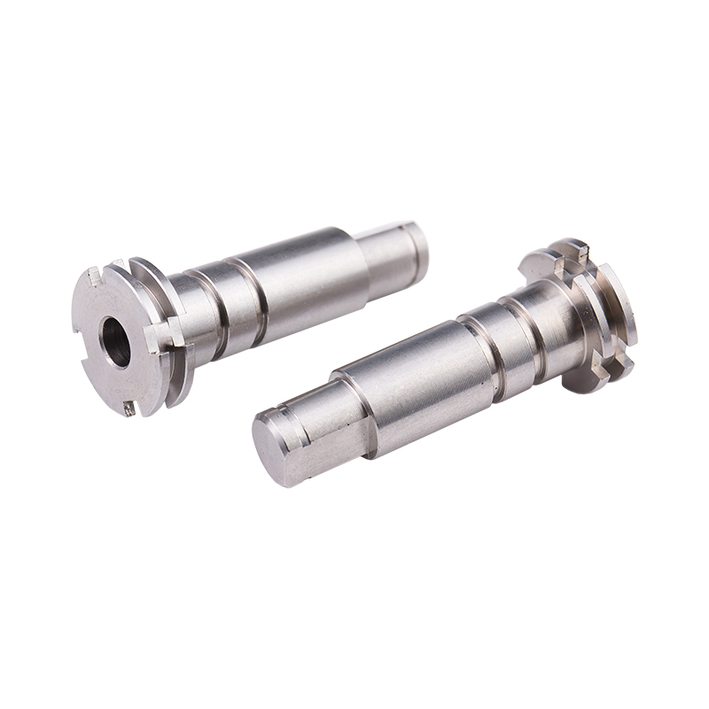 Custom Stainless Steel Drive Stepped ShaftA custom turned stainless steel stepped shaft for motor, bearing, or accessory connection, worth reviewing for repeatable stepped-shaft production and drive-component accuracy.View Product →
Why the Face Often Matters More Than the Diameter
On parts that stack, seat or spin, the end face is the reference everything else is measured from. Optical shafts are a good illustration: the face has to be flat and square so the assembly sits true, with no run-out introduced at the shoulder. The same logic applies to valve bodies, gear blanks and drive components, where a few micrometres of face error turns into noise, vibration or premature wear downstream. That is a large part of how dimensional accuracy is kept under control in volume production.
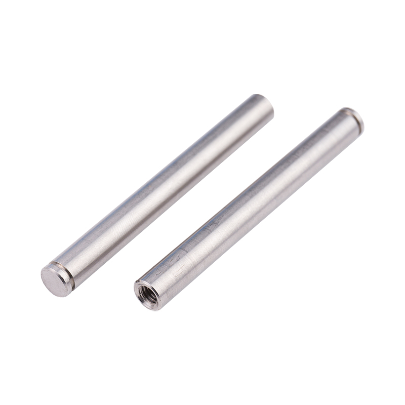 Custom Stainless Steel Optical Shaft With SlotA turned stainless steel optical shaft with slot for movable joint components, made to custom specifications; worth checking where square end faces matter.View Product →
Mating Faces on Bushings and Housings
Bushings show the other side of the coin. A flanged or plain bronze bushing is pressed into a housing and carries a rotating shaft, so both end faces need to be square to the bore and free of raised burrs. A burr left on a faced end can stop the bushing seating fully, which throws off clearance and shows up later as heat and wear. A clean facing pass followed by a light chamfer costs almost nothing and prevents that entirely.
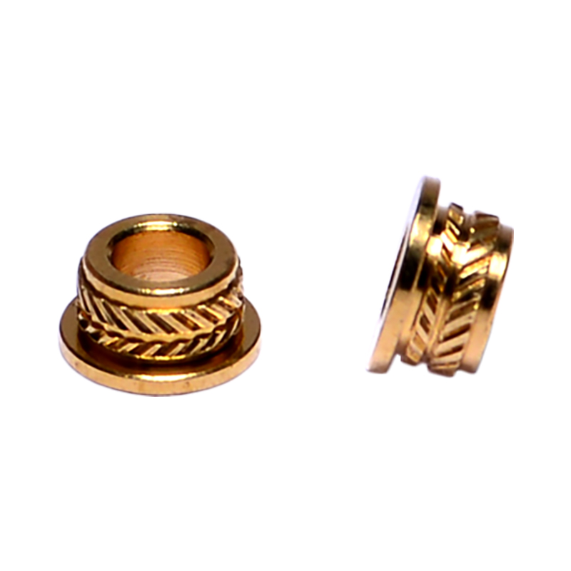 Custom Bronze Bushings for B2B ManufacturingA bronze bushing option customized for business-to-business needs; worth viewing when seating accuracy, burr-free faces, and clean facing are important in housing and shaft assemblies.View Product →
Checklist Before Your Next Facing Cut
- Confirm the workpiece is gripped securely with minimum overhang.
- Set the tool tip exactly on center and check it with a test cut.
- Keep tool overhang to the shortest length that clears the job.
- Decide the feed direction before starting and stay consistent through the batch.
- Rough heavy, then take a light finishing pass for flatness and finish.
- Check the face with a straight edge or indicator, not just by eye.
- Break the edge with a small chamfer or deburring pass before the part leaves the machine.
Facing rewards patience more than power. Get the tool on center, keep the setup rigid, and let a light finishing pass do the work, and the face will be flat, repeatable and ready for whatever operation comes next.
Kunshan Hong Yong Sheng Precision Hardware Products machines and moulds parts of exactly this kind, from shaft cores and bushings to fasteners and injection-moulded components. If you have a drawing where a faced end has to hold a tolerance, our engineers are glad to talk through how it would run in production.
Our Products //
Hot Products

If you are interested in our products, please consult us
Kunshan Hong Yong Sheng Precision Hardware Products Co.,Ltd. All Rights Reserved. Customised Fastener Manufacturer in China
