

 русский
 Español
 中文简体
中文简体

Bush Machining Explained: Materials, Tolerances, and CNC Best Practices
Industry News-A bushing is a small, unglamorous part that quietly decides how long a machine stays in service. It sits between a rotating or sliding shaft and its housing, absorbs the wear, and gets replaced long before the shaft or the casting around it is ruined. Bush machining is the craft of turning those cylindrical liners from bar stock, in bronze, carbon steel, stainless steel, brass, aluminium, or engineering plastic, and holding the inner diameter, outer diameter, concentricity, and surface finish inside tolerances that keep the assembly tight, quiet, and long-lasting. At Kunshan Hong Yong Sheng Precision Hardware Products Co., Ltd. (Hongyongsheng), bushings sit alongside bolts, nuts, shafts, and moulded parts in our everyday production mix, so this guide gathers the practical points we rely on when a drawing calls for a bushing.
Content
- 1 What Bush Machining Actually Means
- 2 Materials and What They Ask of the Cutting Tool
- 3 From Bar Stock to Finished Bushing: The Machining Sequence
- 4 Fits, Tolerances, and Surface Finish
- 5 Where Machined Bushings Earn Their Keep
- 6 Problems That Show Up on the Shop Floor
- 7 Inspection: The Step That Protects the Fit
- 8 Choosing a Bush Machining Partner
What Bush Machining Actually Means
A bushing is a plain bearing. There are no balls or rollers inside it, no cage, no inner ring; the shaft rides directly on the bore, separated by a film of oil, grease, graphite, or embedded lubricant. That simplicity is exactly why machinists keep making them. A plain bearing tolerates shock loads, dirt, and tight packaging far better than a rolling element bearing of the same envelope, and it is inexpensive enough to be treated as a wear item rather than a permanent component.
In practice, bush machining comes down to producing a cylinder with two critical surfaces that must agree with each other. The outer diameter has to lock into the housing, often with light interference. The inner diameter has to carry the shaft with a controlled clearance. The two diameters must share a common axis, and both end faces have to be square to that axis. Add a lubrication groove, an oil hole, a flange, or a keyway, and the job becomes a small exercise in sequence planning: deciding which feature gets cut while the part is still rigid enough to hold.
The term "bush facing" describes one of those operations, squaring and smoothing the end face after the outside has been turned, so the finished cylinder seats flat in its housing instead of rocking on a burr.
Materials and What They Ask of the Cutting Tool
Material choice drives tool geometry, cutting speeds, and even how the finished part is measured. The table below summarises how the families we machine most often behave on a CNC lathe.
| Material | Machining behaviour | Typical bushing use |
|---|---|---|
| Sintered and cast bronze | Free-cutting but porous; sharp tools and light coolant keep the pores open | Pump and motor bearings, conveyor pivots |
| Brass and copper alloys | Gummy and prone to smearing; positive rake and higher surface speed help | Valve adjusters, sealed fittings |
| Carbon and alloy steel | Predictable, but work-hardens if rubbed; rigid boring bars and steady feed | Press-fit housings, suspension pivots |
| Stainless steel | Work-hardens quickly; no dwell, constant feed, generous coolant | Food, medical, and marine equipment |
| Aluminium | Built-up edge on the tool edge; polished flutes and generous rake | Lightweight housings, trim mechanisms |
| Engineering plastics | High thermal expansion; soft jaws, air blast, measure after cooling | Medical, fire-fighting, and harness components |
There is one trap that catches newcomers with plastics: the part measured straight off the machine is not the part that will be shipped. PEEK, PSU, and similar materials grow and shrink noticeably with temperature, so a bore checked while the material is still warm can read several hundredths of a millimetre away from its final size. Let it cool, then measure.
Sintered bronze has the opposite problem. Its value comes from the oil held in thousands of tiny pores, and a heavy flood of coolant can carry chips and cutting fluid into those pores and seal them shut. Light, clean coolant or an air blast usually keeps the bearing self-lubricating the way it was designed to be.
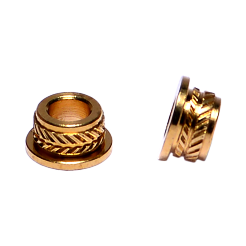 Bronze bushingsLathe Machine Facing: A Manufacturer's Guide to Techniques and Best Practices 21 Sep, 2026 Facing is one of the most common operations performed on a lathe machine, ye...View Product →
From Bar Stock to Finished Bushing: The Machining Sequence
The order of operations matters more than any single cut. A sequence we return to again and again looks like this:
- Saw or part off a blank with enough length for facing and chucking.
- Face one end and turn a clean gripping diameter so later operations repeat accurately.
- Rough turn the outer diameter and rough bore the inner diameter, leaving 0.3 mm to 0.5 mm for finishing.
- Finish the bore by turning, or by reaming to size for small diameters or interrupted bores.
- Finish the outer diameter to the press-fit dimension while the part is still in the same setup, which keeps the two diameters concentric.
- Cut oil grooves, lubrication holes, or spiral channels, keeping the groove edges clean and free of burrs.
- Chamfer the bore entry and break every sharp edge so the shaft and the housing slide into place without scraping.
- Part off or complete the second face, then deburr both ends.
- Clean, measure, and inspect before the part goes anywhere near a box.
Keeping the bore and the outer diameter in one setup is the single biggest favour you can do for concentricity. Every time a bushing is moved to a second chucking, a small amount of runout comes along with it, and no amount of inspection afterwards can remove it.
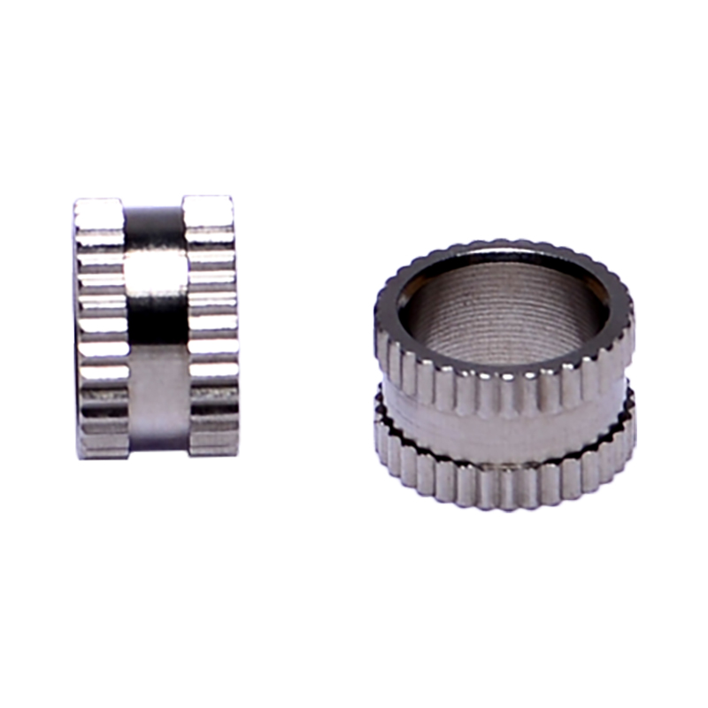 Steel bushingsLathe Machine Facing: A Manufacturer's Guide to Techniques and Best Practices 21 Sep, 2026 Facing is one of the most common operations performed on a lathe machine, ye...View Product →
Fits, Tolerances, and Surface Finish
Two numbers decide whether a bushing runs for years or squeals for a week: the interference between the bushing and the housing, and the clearance between the bushing and the shaft. Both depend on load, speed, temperature, and lubrication, so the drawing always wins. The figures below are the starting points we suggest when a customer asks for a sensible default.
| Feature | Starting point at 25 mm nominal | What it achieves |
|---|---|---|
| Housing press fit | 0.02 to 0.05 mm interference | Holds the bushing against rotation and creep |
| Running clearance | 0.02 to 0.06 mm | Leaves room for a lubricant film under load |
| Slip fit | 0.05 to 0.12 mm | Suits low-speed pivots assembled by hand |
| Concentricity | 0.01 to 0.02 mm total indicator reading | Keeps wall thickness even and load balanced |
| Bore finish | Ra 0.4 to 1.6 micrometres | Supports the oil film without polishing away lubricant pockets |
Surface finish deserves a word of its own. A mirror-polished bore is not automatically better than a carefully controlled one. Extremely smooth bores can struggle to hold oil, while a bore that is too rough wears the shaft and traps debris. A finish in the middle of the range, with the tool lay running around the bore rather than along it, usually performs best.
Getting Lubrication Grooves Right
An oil groove is a hydraulic feature, not decoration. A groove that is too shallow will not feed lubricant along the bore, while one that is too deep cuts into the load-carrying area and reduces the effective bearing surface. In most applications the groove depth stays around one to two millimetres, with generous radii at the ends so the lubricant flows instead of shearing, and the groove edges are deburred carefully, because a raised edge acts like a scraper against the shaft.
Spiral grooves are common where the shaft rotates and lubricant must travel, while axial grooves suit reversing or oscillating motion. For a bushing that is simply pressed in and forgotten, an oil hole plus a shallow circumferential channel is often all the design needs.
Where Machined Bushings Earn Their Keep
Bushings appear wherever a pivot, hinge, or rotating joint has to survive vibration and dirt. Automotive seat frames, door hinges, and pedal assemblies rely on them. Hydraulic pumps and cylinders use bronze and steel bushings to guide pistons and control valves. Conveyor systems, agricultural implements, and machine tool slides all depend on them. The same pattern shows up in medical and fire-fighting equipment, where a bushing frequently pairs with a machined shaft core inside a valve or pump sub-assembly.
Two application details change the machining plan more than anything else. First, whether the bushing will be lubricated in service or must run dry with embedded lubricant, because that decides the material and the groove layout. Second, whether the surrounding housing is rigid or flexible, since a soft housing deforms under press-fit stress and steals part of the clearance you carefully machined into the bore.
Problems That Show Up on the Shop Floor
Most bushing defects trace back to setup rather than to the cutting tools themselves. The list below covers the issues we correct most often.
- Chatter in a thin-walled bore: shorten the unsupported length, use a heavier boring bar, and keep the feed steady instead of slowing it to a crawl.
- Taper or a bell-mouthed bore: check tool deflection and bar overhang, then take a light spring pass to clean up the last few hundredths.
- Ovality after the chuck is released: thin walls deform under jaw pressure, so switch to soft jaws or a collet and keep clamping force light.
- Size drift across a production run: thermal growth is usually the cause, so check the first, middle, and last part of the batch.
- Burrs where a groove meets the bore: a light chamfer or a dedicated finishing pass keeps assembly clean and protects fingers.
- Clogged pores in sintered bronze: replace flood coolant with an air blast and clean the part before it is packed.
Inspection: The Step That Protects the Fit
No amount of careful cutting rescues a bushing that was never measured properly. A basic routine covers the bore size at both ends and in the middle, the outer diameter, wall thickness around the circumference, concentricity between the two diameters, squareness of the faces, and the surface finish of the running bore. Bore gauges, micrometers with ball anvils, plug gauges, and a roundness check on a suitable fixture all have their place.
For tighter work, temperature control matters as much as the instrument. Measuring a warm part with a cold gauge is a reliable way to start an argument that nobody wins. The methods behind how we maintain dimensional accuracy apply directly to bush machining: a stable environment, calibrated instruments, and a first-article check before the run continues.
Choosing a Bush Machining Partner
Most of the effort in a bushing programme happens before the first chip is cut: choosing the material, agreeing the fits, deciding the groove layout, and planning how the part will be measured in production. A supplier who understands that side of the job saves far more time than one who simply quotes the lowest piece price.
Hongyongsheng machines bushings in bronze, steel, brass, stainless steel, aluminium, and engineering plastics, and we also mould polymer components, which means a metal bushing and its plastic housing can be developed together instead of on two separate schedules. Standard fasteners, non-standard parts, shaft cores, and automotive components all pass through the same quality routine, whether the batch is a few hundred pieces or a running order.
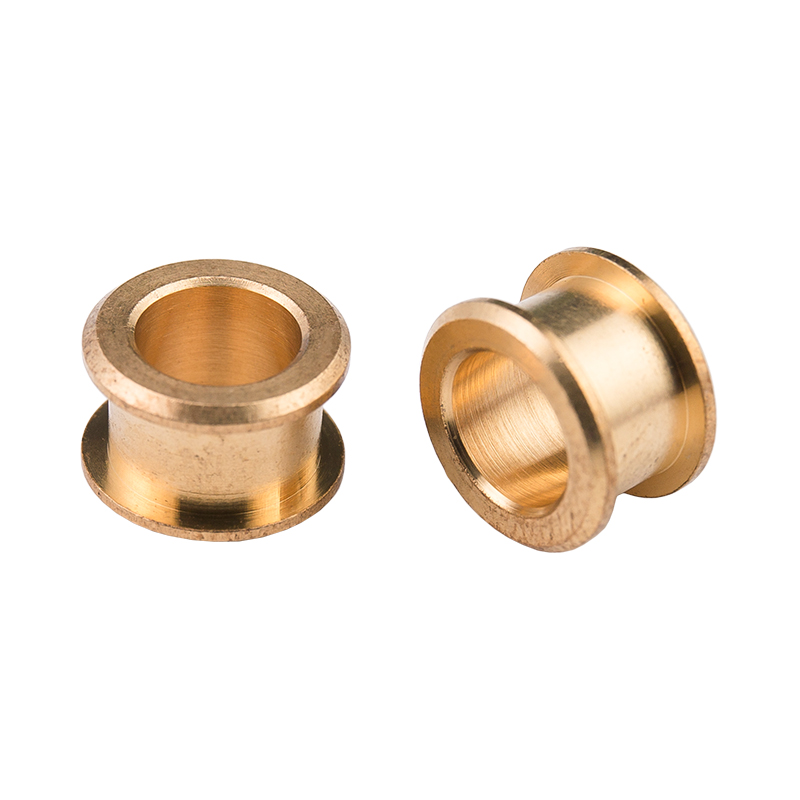 Bushings FactoryBare Circle BushingsView Product →
Bush machining rewards patience more than speed. Get the material right, cut the bore and the outer diameter in one setup, respect the clearance the application actually needs, and measure before you ship. A bushing that meets those four conditions will outlast several shafts, and the machine it lives in will thank you for it. If you would like a second opinion on a drawing, Hongyongsheng is a precision hardware manufacturer based in Kunshan and happy to review fits, materials, and tolerances with you before anything is cut.
Our Products //
Hot Products



If you are interested in our products, please consult us
Kunshan Hong Yong Sheng Precision Hardware Products Co.,Ltd. All Rights Reserved. Customised Fastener Manufacturer in China
