

 русский
 Español
 中文简体
中文简体

Facing in Lathe: Definition, Techniques, Best Practices, and Common Mistakes
Industry News-When a cylindrical blank comes off a saw, its end is neither flat nor square. Facing on a lathe is the operation that fixes that: a single-point tool squares the end, creates a flat reference surface, and brings the part to a controlled length. Without a good face, every later operation has no reliable datum. With a good face, turning, drilling, boring, and threading all have a solid foundation. Facing is one of the most common lathe operations, and also one of the most often mishandled in tool height, feed direction, and spindle speed. This article explains what facing in a lathe is, how it differs from turning, which feed direction to choose, how to set up the tool, what parameters produce a clean face, and why it matters in precision manufacturing.
Content
What Is Facing in a Lathe?
Facing in a lathe is the removal of material from the end face of a rotating workpiece using a single-point cutting tool. The workpiece rotates about its own axis while the tool feeds perpendicular to that axis, sweeping from the outside diameter toward the center or from the center outward. The result is a flat surface that is perpendicular to the spindle axis and square to the workpiece centerline.
Facing does three jobs in a typical machining sequence. First, it establishes a clean datum face. Saw-cut, cast, or forged blanks have rough, uneven ends, and facing removes the irregular layer so other dimensions have a reliable starting point. Second, it controls the overall length of the part, because taking a measured cut from the end brings the part to the length specified on the drawing. Third, it produces the required surface finish, which can range from a simple deburred edge to a fine face that later acts as a sealing or mating surface.
Facing vs. Turning: What Is the Difference?
Turning and facing happen on the same machine with the same tool, but they create different geometries and need different handling. In turning, the tool feeds parallel to the spindle axis and creates a cylindrical outside surface. The tool stays at an almost constant radius, so the cutting speed at the edge is stable. Turning produces diameters, shoulders, tapers, and grooves. In facing, the tool feeds perpendicular to the spindle axis and creates the flat circular face on the end of the part.
| Aspect | Turning | Facing |
|---|---|---|
| Feed direction | Parallel to the workpiece axis | Perpendicular to the workpiece axis |
| Surface produced | Cylindrical surface | Flat circular end face |
| Primary purpose | Diameters, shoulders, grooves | Length control, square datum face |
| Cutting speed | Nearly constant along the cut | Drops to zero at the center |
| Speed control mode | Fixed spindle speed is acceptable | Constant surface speed is preferred |
The practical difference is cutting speed. A facing tool starting at the outside edge of a 50 mm bar cuts at the full surface speed of that diameter; by the time it reaches the center, the cutting speed is zero. On a CNC lathe, constant surface speed mode raises spindle rpm as the tool moves inward, keeping the finish even. On a manual lathe, the operator accepts the variation and takes a light finishing pass with a sharp tool to keep the face clean.
Which Feed Direction Should You Use for Facing?
Few machining questions produce as much debate as whether to face from the outside diameter toward the center or from the center outward. Both directions work. The right choice depends on tool orientation, part rigidity, and where the finish must be best.
Feeding outside-to-center is the conventional choice because it uses the same tool orientation as normal external turning. The tool starts at the outer edge, where cutting speed is highest, and moves inward. If the tool tip is set exactly on center, the face cleans up completely. The catch is that near the center the cutting speed approaches zero. A tool positioned slightly off center can start rubbing and leave a small pip in the middle of the face.
Feeding center-to-outside avoids that pip. The tool starts at the center and moves outward, which keeps the cutting edge in compression through the whole pass. Many machinists prefer this for finishing cuts, especially when the full face must be smooth or when a center hole must be respected. The downside is that the cross-slide feed has to be reversed, and not every tool holder is set up for it.
The practical rule is straightforward: use outside-to-center for roughing, and switch to center-to-outside for the finishing pass whenever the face has to be clean across its full diameter. Keep the tool sharp and the tip on the centerline in both cases.
Tool Setup for Facing
Tool setup decides the quality of a facing cut before the spindle starts. The tool tip must sit exactly on the spindle centerline. Set below center, the edge cannot reach the true center point, so a pip remains in the middle of the face. Set above center, the same pip appears and the tool can rub on its trailing edge. Checking tool height against a tailstock center takes seconds and prevents one of the most common facing defects.
Rigidity is the second factor. A tool with too much overhang, or a boring bar pressed into facing service, deflects under the axial cutting force and leaves a slightly concave face. Keep the overhang as short as the setup allows. Use inserts with positive geometry, because they cut with less force, and choose a nose radius around 0.2 to 0.4 mm for a good finish without excessive pressure on thin-walled workpieces.
Cutting Parameters for a Clean Face
Select the surface speed for the workpiece material at its outside diameter. For mild steel with carbide inserts, that is usually 100 to 150 m/min; for aluminum, 200 to 300 m/min; for stainless steel, 80 to 120 m/min. Use a feed between 0.05 and 0.15 mm/rev for finishing and a depth of cut around 0.25 to 0.5 mm.
On a CNC lathe, enable constant surface speed so the spindle ramps up as the tool approaches the center; this keeps the finish uniform. Make sure the workpiece is clamped firmly enough to handle the rising torque. On a manual lathe, set the spindle speed for the outside diameter and keep the feed light. For gummy materials, cutting fluid prevents the chip from welding onto the face and tearing the surface.
Common Facing Problems and How to Fix Them
| Problem | Likely Cause | Practical Fix |
|---|---|---|
| Pip at the center | Tool tip below or above centerline | Set tool height exactly on center |
| Concave face | Tool deflection under cutting force | Reduce overhang, use a positive-geometry insert, lower feed |
| Chatter marks | Poor rigidity or unfavorable speed | Stiffen the setup, change spindle speed, reduce feed |
| Torn or rough finish | Dull insert or gummy material | Replace the insert, apply cutting fluid, reduce feed |
| Burr on the outer edge | Material pushed past the edge | Take a chamfer pass or deburr by hand |
Most facing defects trace back to the same root causes: tool height, rigidity, or cutting parameters. If the face is not flat, check for deflection first. If there is a pip, check the tool height. If the finish is torn, the insert is dull or the feed is too high. Fixing these basics solves more facing problems than any machine adjustment.
Facing in Precision Manufacturing
Facing matters in production because it creates the surfaces that other components mate against. A bushing seated in a housing needs square, flat end faces. A stepped shaft that locates a bearing and a gear depends on faced shoulders for correct positioning. A valve nut that seals against a port must have a clean, flat face to hold pressure. In each part, the facing operation sets the reference geometry for the whole component.
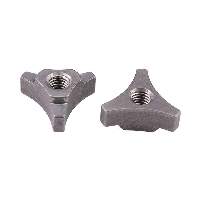
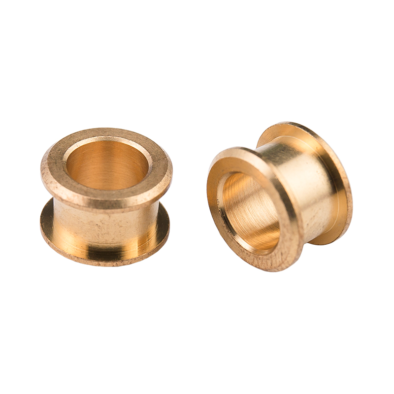
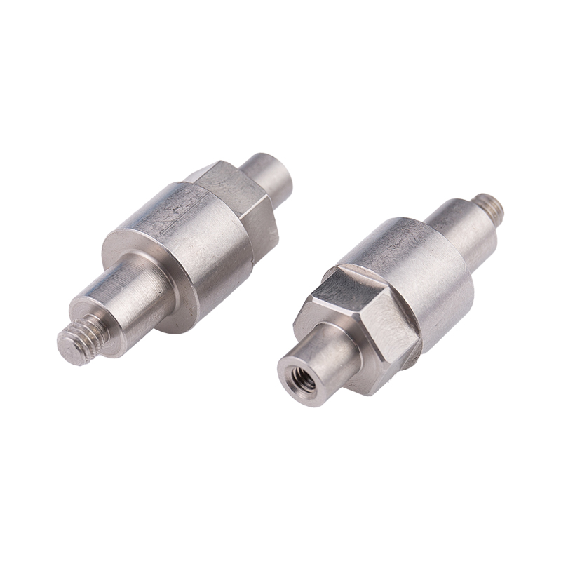
At Kunshan Hong Yong Sheng Precision Hardware, facing and turning are part of the daily routine for components like precision stepped shafts, where each shoulder face must be square to the axis so that bearings and gears seat correctly. The same logic applies to bushings for rotating assemblies: if the end faces are not flat and square, the bushing will not sit properly in its housing, and the assembled unit carries the error. Even small components such as copper hydraulic valve adjustment nuts depend on facing, because their sealing faces have to stay flat and parallel under hydraulic pressure.
 Custom Copper Hydraulic Valve Adjustment Nuts Manufacturers, SuppliersKunshan Hong Yong Sheng Precision Hardware Products Co.,Ltd is China custom Copper Hydraulic Valve Adjustment Nuts Manufacturers and Supp...View Product →
 OEM/ODM Customised Bushings Factory, Exporter In ChinaKunshan Hong Yong Sheng Precision Hardware Products Co.,Ltd is leading customized Bushing factory and exporter in China, our company OEM/...View Product →
 Custom Stepped Shaft Manufacturer, SupplierKunshan Hong Yong Sheng Precision Hardware Products Co.,Ltd is famous Stepped Shaft manufacturers and suppliers in China, we offer custom...View Product →
Running faced parts at volume takes more than a good finish; it takes dimensional accuracy that holds from the first piece to the last. A production shop that verifies dimensional accuracy on those features catches drift before it becomes scrap. That discipline also carries into capacity growth: when a precision hardware manufacturer expands production, it has to hold the same facing tolerances across larger batches and faster cycles without letting quality slip.
Our Products //
Hot Products

If you are interested in our products, please consult us
Kunshan Hong Yong Sheng Precision Hardware Products Co.,Ltd. All Rights Reserved. Customised Fastener Manufacturer in China
