

 русский
 Español

Why Is a Brass Double-Thread Worm Gear the Ideal Choice for Motor-Driven Cross-Axis Power Transmission?
Industry News-Content
- 1 What Is a Brass Double-Thread Worm Gear?
- 2 Why Brass Is the Material of Choice
- 3 Understanding the Double-Thread Design and Its Effect on Gear Ratio
- 4 Transmitting Power Between Offset Axes
- 5 Advantages of Smooth Rotation and High Gear Ratio in Motor Applications
- 6 Typical Application Fields
- 7 Lubrication and Service Considerations
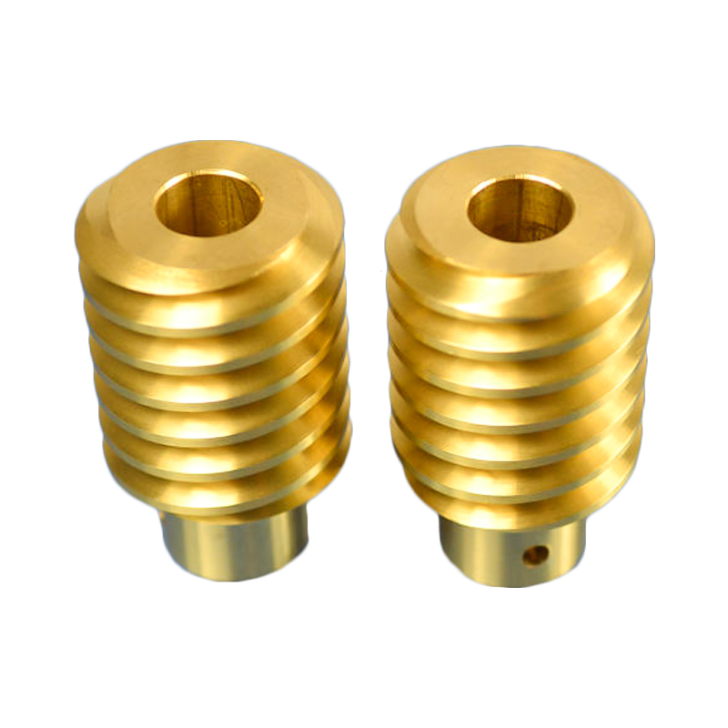
What Is a Brass Double-Thread Worm Gear?
A worm gear is a type of gear in which a screw-like shaft — called the worm — meshes with a toothed wheel called the worm wheel or worm gear. The double-thread variant, as the name indicates, features two helical threads wound around the worm shaft rather than one, which directly affects the gear ratio and output speed characteristics of the transmission system. This specific component is machined from brass through a turning process, producing a part with tight dimensional tolerances, a smooth surface finish, and material properties well suited to the demands of motor-driven mechanical systems.
The brass double-thread worm gear is primarily used in conjunction with an electric motor to transmit motion and power between two shafts that are oriented at an angle to each other — most commonly at 90 degrees. Unlike parallel-shaft or bevel gear systems, the worm gear arrangement allows the driving and driven shafts to be non-intersecting and non-parallel, making it an exceptionally versatile solution for compact mechanical assemblies where spatial constraints prevent conventional shaft alignment. The combination of high gear reduction, smooth and quiet operation, and the inherent mechanical properties of brass makes this component a reliable choice across a broad range of industrial and commercial applications.
Why Brass Is the Material of Choice
The selection of brass as the manufacturing material for worm gears is not arbitrary — it is the result of a well-established understanding of how this copper-zinc alloy performs under the specific mechanical and tribological conditions present in worm gear drives. Worm gear contact is characterized by high sliding velocity between the worm thread and the gear tooth surface, a condition that generates significant friction and heat if incompatible materials are paired together. Brass offers a combination of properties that directly addresses this challenge.
- Low friction coefficient: brass has a naturally low coefficient of friction against steel, which is the typical material used for the mating worm shaft. This reduces heat generation, minimizes power loss through friction, and extends the service life of both components significantly.
- Good machinability: brass is one of the most machinable metals available, allowing the complex helical tooth profile of a double-thread worm gear to be cut with high precision on a lathe or CNC turning center. This machinability also keeps manufacturing costs reasonable even for precision-grade components.
- Adequate strength and hardness: while softer than steel, brass provides sufficient tensile strength and surface hardness for the load levels typical in motor-coupled worm gear drives, particularly in medium-duty applications where extreme shock loading is not a concern.
- Corrosion resistance: brass resists oxidation and corrosion in most operating environments, making it suitable for use in both indoor industrial settings and in equipment exposed to moderate humidity without requiring protective coatings.
- Thermal conductivity: brass conducts heat more effectively than many engineering plastics used as alternative worm gear materials, helping to dissipate the frictional heat generated during continuous operation and preventing thermal degradation of lubricant films.
In practice, the conventional pairing is a hardened steel worm shaft meshing with a brass worm gear wheel. This dissimilar material combination is deliberately chosen because it minimizes adhesive wear — the tendency of sliding surfaces made from the same material to micro-weld and tear during contact. The harder steel worm cuts cleanly against the brass wheel surface, and any minor wear that does occur preferentially removes material from the softer brass rather than damaging the steel worm, which is the more costly and difficult component to replace.
Understanding the Double-Thread Design and Its Effect on Gear Ratio
The number of threads on a worm shaft — referred to as the number of starts — is one of the most fundamental design parameters in a worm gear system because it directly determines the gear ratio achievable for a given number of teeth on the worm wheel. This relationship is expressed by a straightforward formula: gear ratio equals the number of teeth on the worm wheel divided by the number of starts on the worm shaft.
A single-start worm advances the worm wheel by exactly one tooth per full revolution of the worm shaft. A double-thread (two-start) worm advances the wheel by two teeth per revolution. This means that for the same worm wheel tooth count, a double-thread worm produces half the gear ratio of a single-thread worm but delivers twice the output speed. Conversely, to achieve the same gear ratio as a single-thread worm with a double-thread worm, the wheel must have twice as many teeth — which increases the wheel diameter and the overall size of the gear pair.
Gear Ratio Comparison by Thread Count
| Worm Thread Count | Worm Wheel Teeth | Resulting Gear Ratio | Typical Application |
| Single-start | 40 | 40:1 | Very high reduction, self-locking |
| Double-start | 40 | 20:1 | High reduction, higher efficiency |
| Triple-start | 40 | 13.3:1 | Moderate reduction, high efficiency |
| Four-start | 40 | 10:1 | Low reduction, near-reversible |
The double-thread design occupies a useful middle ground in this spectrum. It offers substantially higher gear ratios than are achievable with spur, helical, or bevel gear pairs in a single stage, while maintaining better mechanical efficiency than single-start worm gears. This makes the double-thread brass worm gear particularly well suited to applications where significant speed reduction is needed from a motor — such as reducing a 1,400 RPM motor output to 70 RPM for a conveyor drive — without the severe efficiency penalty associated with very high-ratio single-start worm drives.
Transmitting Power Between Offset Axes
One of the defining functional characteristics of the worm gear arrangement is its ability to transmit rotational motion and torque between two shafts that are neither parallel nor intersecting — a configuration referred to as crossed-axis or offset-axis transmission. In the standard configuration, the worm shaft and the worm wheel shaft are arranged at 90 degrees to each other, with a center distance between their axes that is determined by the gear geometry. This arrangement is fundamentally different from bevel gears, which require intersecting axes, and from spur or helical gears, which require parallel axes.
This geometric flexibility is extremely valuable in mechanical design. It allows engineers to route power transmission around corners within a compact assembly without the need for intermediate shafts, universal joints, or additional gear stages. A motor mounted horizontally can drive a vertical output shaft, or a vertically mounted motor can power a horizontal conveyor — all within the footprint of a single gearbox housing containing the worm and wheel pair. The compactness of this solution is one reason worm gear reducers are so prevalent in material handling, packaging, and automation equipment.
The brass double-thread worm gear is typically the driven component in the pair — it receives motion from the steel worm shaft that is coupled directly to the motor output. As the worm rotates, its helical threads engage the teeth of the brass wheel in a continuous sliding and rolling contact, pushing each tooth in sequence and causing the wheel to rotate about its own axis. The smooth, progressive tooth engagement characteristic of the helical geometry produces a gradual, even torque transfer rather than the impulsive contact that can occur in straight-tooth gear pairs, which is the primary reason worm gear drives are inherently quiet and smooth in operation.
Advantages of Smooth Rotation and High Gear Ratio in Motor Applications
When a brass double-thread worm gear is paired with an electric motor, the combination delivers a set of performance characteristics that are difficult to match with alternative gear technologies at comparable size and cost. These advantages make the worm gear drive a default choice for a wide range of motor-driven machinery.
Vibration-Free, Quiet Operation
The helical thread profile of the worm ensures that tooth engagement is gradual rather than sudden. At any given moment, multiple points along the thread length are in contact with the wheel tooth, distributing the load across a larger contact area and preventing the impact-driven vibration and noise that afflicts straight-cut gear systems. This smooth engagement makes worm gear reducers the preferred choice in applications where noise is a concern — office equipment, medical devices, food processing machinery, and consumer appliances all benefit from this inherently quiet transmission characteristic.
Large Gear Ratio in a Single Stage
A single worm gear stage can achieve gear ratios ranging from 5:1 to over 100:1, depending on thread count and wheel tooth number. Achieving a comparable ratio with spur or helical gears would require two or three separate gear stages in series, each adding complexity, cost, weight, and potential failure points to the gearbox. The worm gear drive achieves this large ratio in a single mesh, resulting in a gearbox that is dramatically more compact and mechanically simpler than multi-stage alternatives at the same reduction ratio.
Self-Locking Capability
At lower lead angles — which correspond to higher gear ratios and fewer thread starts — worm gear drives exhibit self-locking behavior: the gear cannot be back-driven from the output shaft. This means that when the motor stops, the load cannot cause the output shaft to rotate backward, providing a built-in mechanical brake without any additional components. While double-thread worms have a higher lead angle than single-thread worms and may not self-lock under all conditions, they still offer significantly greater resistance to back-driving than most other gear types. This property is exploited in lifting equipment, gate operators, and positioning systems where holding a load stationary after motor shutdown is a safety or functional requirement.
Typical Application Fields
The practical utility of brass double-thread worm gears in motor-driven systems spans an exceptionally wide range of industries and product categories. Their combination of high reduction ratio, cross-axis geometry, quiet operation, and compact form factor makes them suitable wherever a motor needs to drive a relatively slow output shaft at high torque without complex multi-stage gearboxes.
- Conveyor and material handling systems: motor-driven worm gear reducers control the speed of conveyor belts, roller tables, and sorting systems in warehouses, production lines, and logistics facilities
- Valve and gate actuators: worm gear drives convert motor rotation into the high torque needed to open and close large industrial valves, sluice gates, and flood barriers
- Lifting and hoisting equipment: electric winches, small hoists, and stage rigging systems use worm gear reducers for their self-locking capability and high torque output
- Packaging machinery: indexing tables, filling head drives, and labeling equipment use compact worm gear units to achieve precise, repeatable positioning at low output speeds
- Robotics and automation: small-format worm gear pairs provide joint rotation in robotic arms, pan-tilt camera mounts, and automated inspection equipment
- Agricultural equipment: seed drill drives, spreader mechanisms, and irrigation pivot drives use worm gear reducers for their reliability in dusty, outdoor environments
Lubrication and Service Considerations
Effective lubrication is the most critical operational requirement for a brass worm gear drive. Because the contact between worm and wheel is dominated by sliding rather than rolling, the lubricant film must be maintained at all times to prevent metal-to-metal contact, which would cause rapid wear of the brass wheel surface. Most worm gear reducers are lubricated with a dedicated worm gear oil — typically a high-viscosity mineral or synthetic oil with extreme pressure (EP) additives formulated specifically for the sliding contact conditions of worm drives. Standard gear oils designed for helical or spur gears are not suitable substitutes because they lack the film-forming properties needed under worm gear sliding conditions.
Oil level should be checked regularly and maintained at the manufacturer's specified fill mark. Oil change intervals depend on operating temperature, duty cycle, and whether synthetic or mineral oil is used — typical intervals range from 2,000 to 5,000 hours of operation. Operating a worm gear drive at elevated temperatures accelerates lubricant oxidation and degradation, so thermal management through adequate housing ventilation or external cooling should be considered for continuous-duty applications. Periodic inspection of the brass wheel teeth for signs of pitting, scoring, or uneven wear provides early warning of lubrication or alignment problems before they progress to catastrophic gear failure.
Our Products //
Hot Products
If you are interested in our products, please consult us
Kunshan Hong Yong Sheng Precision Hardware Products Co.,Ltd. All Rights Reserved. Customised Fastener Manufacturer in China
