

 русский
 Español
 中文简体


Facing on a Lathe: Setup, Cutting Steps and Practical Shop Tips for Clean Faces
Industry News-Facing is usually the first cut a new machinist learns and the last one an experienced hand stops thinking about, which is exactly why it still causes trouble. Chuck a workpiece, take a pass across the end, and you have a flat, square face to work from. Do it carelessly and every operation that follows inherits the error. What follows is how we approach facing on a lathe in our own shop: the setup habits, the numbers we start from, and the faults we end up correcting most often.
Content
What Facing on a Lathe Really Does
Facing removes material from the end of a workpiece to produce a surface perpendicular to the axis of rotation. The tool moves radially, across the face, rather than along the length of the part. The result is a reference face: something to seat against, measure from, or hold on to in a second operation.
Most of the time the workpiece is cylindrical and held in a three-jaw chuck. A four-jaw chuck or a faceplate comes out when the part is irregular, thin-walled, or needs to be dialled in properly. Longer shafts are often run between centres with a drive dog carrying the rotation.
Two things define a good face. It is flat within whatever the drawing allows, and it is square to the axis. Finish, burr condition and cycle time all follow from those two. A face that looks bright but runs out by a few hundredths of a millimetre will still push a bearing out of line, so we check with an indicator rather than by eye.
Facing Versus Turning: Different Feed, Different Result
The two operations are often confused because they use the same machine and frequently the same tool. The difference is the direction the tool travels relative to the work.
| Aspect | Facing | Turning |
|---|---|---|
| Tool feed | Radial, across the end face | Axial, along the length |
| Result | Flat face square to the axis | Reduced diameter, cylindrical surface |
| Depth measured | Off the end, along the axis | Off the diameter, radially |
| Surface speed | Changes as the tool crosses the face | Constant at a given diameter |
| Typical use | Squaring an end, cleaning a saw cut, forming a shoulder | Bringing an outside diameter to size |
Setting Up Before the First Cut
Almost every facing problem we get asked about starts before the tool touches the metal. Five minutes of preparation saves a scrapped part.
- Keep the overhang short. Grip as much of the workpiece as the operation allows; every extra millimetre hanging out of the jaws adds vibration you cannot cut away afterwards.
- Set the tool on centre height. A tool above centre rubs and dulls quickly, one below centre leaves a pip in the middle of the face. Check against the tailstock centre with a rule or a small square.
- Match the tool to the direction of cut. A standard right-hand turning tool held the usual way cuts on the approach side, so you feed from the outside diameter inward with the spindle turning toward you.
- Lock the carriage and set the compound so the cross slide moves the tool squarely across the face. Any angle left in the compound turns a flat face into a cone.
- Clear the swarf and make sure the tool has room to reach the centre of the work without the holder fouling the chuck.
A Facing Sequence That Works
The order below is what we teach on the shop floor. It suits manual lathes and translates directly to a CNC program.
- Skim the end lightly with the spindle running at a moderate speed and watch where the tool first makes contact. A partial cut tells you the workpiece is not sitting square in the jaws or has been sawn at an angle.
- Take the roughing pass from the outer edge toward the centre, leaving about 0.2 mm to 0.5 mm of stock for finishing.
- Retract, stop the spindle and check the overall length against the drawing before going further. It is far easier to remove another 0.3 mm than to put it back.
- Take the finishing cut with a sharp edge, a lighter feed and the same direction of travel, so the finish is consistent across the whole face.
- Stop just short of dead centre on manual machines, or program the tool to clear the centre line on a CNC, then break the edge with a fine file or a deburring tool while the work turns slowly.
One point worth repeating: as the tool approaches the axis, surface speed falls toward zero. Cutting there is closer to rubbing than cutting, which is why the finish often deteriorates in the last few millimetres of the face. A slightly higher spindle speed, a lighter feed near the centre, or constant surface speed control on a CNC all help.
Speeds, Feeds and Depth of Cut
Numbers depend on material, rigidity and tooling, but these are the ranges we start from on a reasonably tight lathe with carbide inserts.
| Parameter | Roughing | Finishing |
|---|---|---|
| Depth of cut | 0.5 mm to 2 mm | 0.1 mm to 0.4 mm |
| Feed per revolution | 0.1 mm to 0.25 mm | 0.05 mm to 0.1 mm |
| Spindle speed | Set from the largest diameter | Can be raised for a cleaner face |
| Coolant | Flood where available | Flood or a light brush application |
Set the spindle speed from the largest diameter you are cutting, not the finished size. For example, a 40 mm face and a 10 mm face need very different rpm to hold the same surface speed, and the outer edge is where most of the cutting happens.
When a Face Goes Wrong
Most facing faults give themselves away in the first few seconds. Reading the surface while cutting saves a lot of guesswork.
- Chatter marks: too much overhang, a loose toolpost, an unsupported workpiece or a feed that is too heavy. Reduce overhang first, then feed.
- Dished or convex face: the tool is not on centre height, or the cross slide is not travelling square to the axis.
- Torn, smeared finish: a dull edge, or a surface speed near the centre that is too low to cut cleanly.
- Heavy burr at the outer edge: a worn insert and a feed rate that is pushing rather than shearing the metal.
- Pip left in the middle: the tool stopped short of the axis, or the tool nose geometry is not suited to facing to centre.
Where Face Quality Shows Up in Real Parts
A face is rarely an end in itself. On a stepped shaft the shoulder that carries a bearing has to sit square to the journal, or preload and runout go out of the window. On a bronze bushing the faced ends set the installed length and decide how the part seats in its housing. Gear blanks get both faces machined so thickness and parallelism fall inside tolerance before the teeth are cut. When those details drift, the whole assembly tells you about it later.
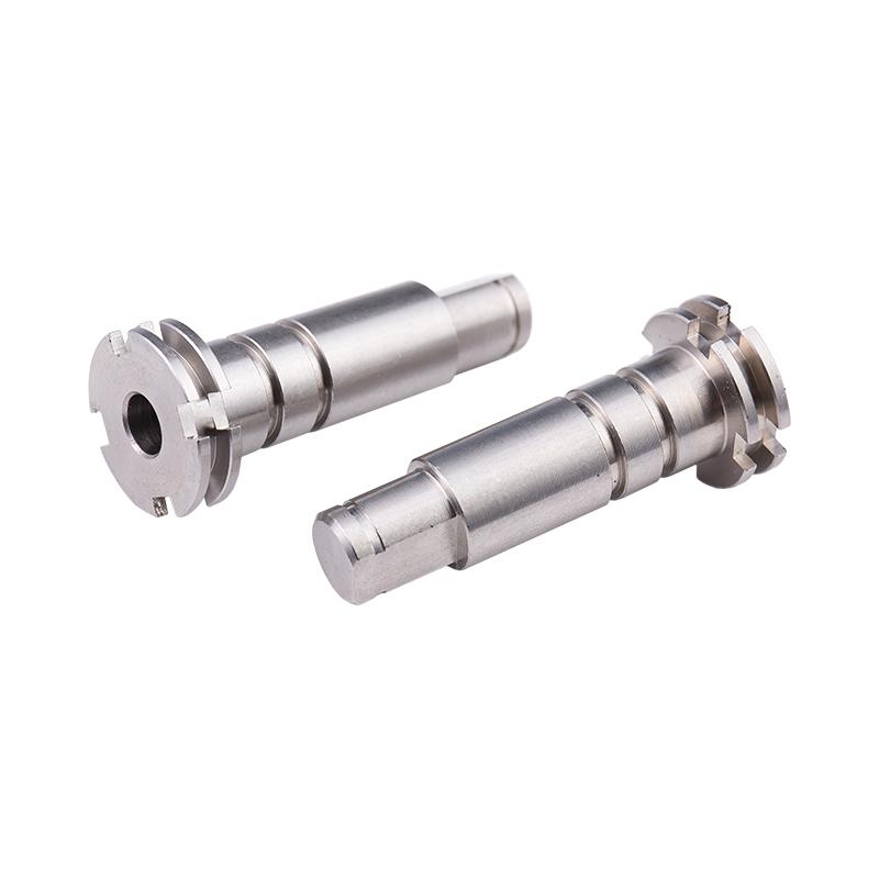 Custom Stainless Steel Drive Stepped ShaftCustom turned stainless steel shaft for motor and bearing connections, with specifications and surface treatment set to the application; shoulder facing supports assembly accuracy.View Product →
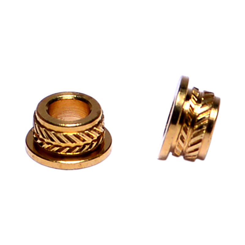 Custom Bronze Bushings for B2B ProductionCustom bronze bushings from a manufacturer offering CNC turning and high-volume output; faced ends help set installed length and seating in housings.View Product →
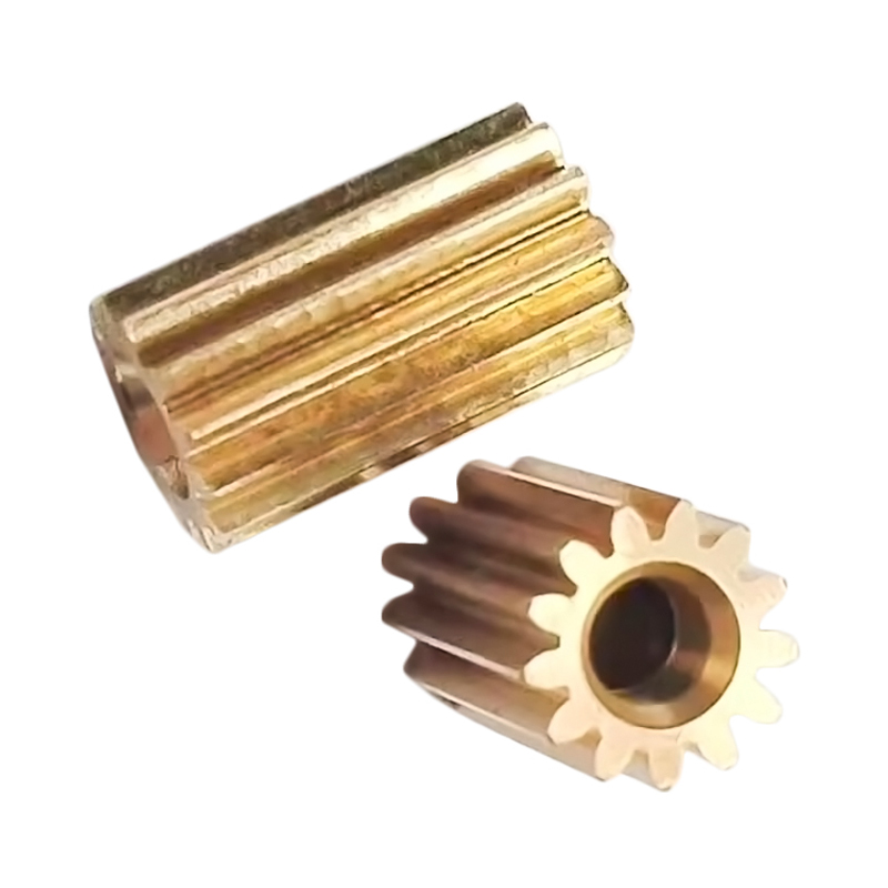 Custom Brass Spur Gear for Power TransmissionBrass-turned spur gear for motor-driven power transmission, processed to requested specifications and surface treatment, with facing critical to thickness and parallelism.View Product →
This is the reason we treat facing as a metrology step rather than a roughing one. The parts leaving our turning cells, from stepped shaft work to small fasteners, are checked for squareness and length rather than simply measured for diameter. Our team has written up the wider approach in how dimensional accuracy is held across a production run, and the facing operation is the first place that discipline starts.
Habits That Keep Faces Flat
Tool life and patience matter more than any single setting. Keep a spare insert or a freshly honed tool within reach so a dull edge never becomes a reason to finish the face badly. Take the extra pass at a lighter depth instead of forcing a heavy cut that deflects the workpiece. Never leave the chuck key in the chuck, keep the file handle in your hand and away from the spinning chuck, and clear long stringy swarf with a hook or a brush rather than with gloved fingers. Small habits like these are what make a shop floor calm, and calm operators cut better faces.
Facing on a lathe is a simple idea carried out with a lot of small decisions: how much hangs out of the jaws, where the tool sits relative to centre, which way it travels, and how much stock you leave for the last pass. Get those right and the operation takes minutes and holds tolerance without fuss. Get them wrong and the error follows the part all the way to assembly. If a face on one of your components keeps drifting out of specification, send us the drawing and a photo of the surface finish, and we will tell you what we would change in the setup.
Our Products //
Hot Products

If you are interested in our products, please consult us
Kunshan Hong Yong Sheng Precision Hardware Products Co.,Ltd. All Rights Reserved. Customised Fastener Manufacturer in China
