

 русский
 Español

Bolt Head Sizes, Pilot Holes, Wedge Anchors & Rivets: Full Guide
Industry News-Content
- 1 Quick-Reference Answers to the Most Common Fastener Size Questions
- 2 Bolt Head Size to Bolt Diameter: The Full SAE Reference Table
- 3 Metric Size Between 3/8 and 7/16: Filling the Gap
- 4 Bolt Head Markings: How to Identify Grade and Manufacturer
- 5 How to Measure Threads Per Inch
- 6 Tap Drill and Hole Sizes: 3/8-16 and Other Common Taps
- 7 Pilot Holes for Wood Screws: #6 Through #14
- 8 What Lag Screws Are Used For
- 9 How Concrete Wedge Anchors Work and How to Use Them
- 10 Pop Rivet Length and Diameter Selection Rules
Quick-Reference Answers to the Most Common Fastener Size Questions
Most fastener sizing questions have a single definitive answer. Here are the most-searched ones up front:
- What size bolt has a 7/16 head? A 1/4-inch bolt (UNC/UNF). A 7/16″ wrench fits a standard 1/4″ hex-head bolt.
- What size bolt has a 1-1/8 head? A 3/4-inch bolt. A 1-1/8″ wrench is the standard fit for a 3/4″ hex bolt.
- Wrench size for a 5/8 nut? A 15/16″ wrench fits a standard 5/8″ nut or bolt head.
- What size bolt takes a 5/8 wrench? A 3/8-inch bolt. A 5/8″ wrench is the standard for 3/8″ hex-head fasteners.
- What size head does a 1/4 bolt have? A 7/16-inch head (standard hex head per ASME B18.2.1).
- What size nut goes on a 3/8 bolt? A 3/8″ nut — nut size is always the same nominal diameter as the bolt, with a 9/16″ wrench required to turn it.
The sections below provide the reference tables, rules of thumb, and techniques behind every common fastener sizing task — bolt head identification, pilot holes, tap drill sizes, rivets, wedge anchors, and more.
Bolt Head Size to Bolt Diameter: The Full SAE Reference Table
The relationship between bolt diameter and hex head size is standardized by ASME B18.2.1 for inch fasteners. The head-across-flats dimension (what your wrench grips) is consistently about 1.5× the bolt diameter for standard hex heads — a useful rule of thumb when you need to estimate without a reference chart.
| Bolt Diameter | Head / Wrench Size | Metric Equivalent (Approx.) |
|---|---|---|
| 1/4″ | 7/16″ | 11 mm |
| 5/16″ | 1/2″ | 13 mm |
| 3/8″ | 9/16″ | 14–15 mm |
| 7/16″ | 5/8″ | 16 mm |
| 1/2″ | 3/4″ | 19 mm |
| 9/16″ | 13/16″ | 21 mm |
| 5/8″ | 15/16″ | 24 mm |
| 3/4″ | 1-1/8″ | 29 mm |
| 7/8″ | 1-5/16″ | 34 mm |
| 1″ | 1-1/2″ | 38 mm |
How to Measure Bolt Head Size
Bolt head size is measured across the flats — from one flat face to the parallel flat face directly opposite, not corner to corner. Use a caliper for accuracy. Corner-to-corner measurement will give a larger number (typically 15% larger) that does not correspond to any wrench size. When calipers are not available, fit wrenches from a set until one slides snugly onto the head without rocking — that is your head size.
For identifying an unknown bolt by head size alone: measure across the flats, then look up the wrench size in the table above to identify the bolt diameter. A 9/16″ head = 3/8″ bolt; a 7/16″ head = 1/4″ bolt; a 1-1/8″ head = 3/4″ bolt.
Metric Size Between 3/8 and 7/16: Filling the Gap
This is one of the most common cross-over questions when working with mixed SAE and metric fasteners. 3/8″ = 9.525 mm and 7/16″ = 11.112 mm, leaving a range of about 1.6 mm between them.
The metric sizes that fall between 3/8″ and 7/16″ are:
- 10 mm — the closest metric wrench size to 3/8″ (10 mm = 0.394″). A 10 mm wrench fits 10 mm hex heads and is frequently close enough to turn 3/8″ fasteners in a pinch, though it is slightly loose.
- 11 mm — sits between 3/8″ and 7/16″. Not a common bolt head size but appears on some automotive fasteners and European equipment.
In practice, 10 mm is the go-to metric substitute when you need something between 3/8″ and 7/16″. For bolt diameters in this range: M10 (10 mm diameter) uses a 17 mm wrench, while the SAE equivalent 3/8″ bolt uses a 9/16″ (14.3 mm) wrench — so they do not substitute for each other at the bolt level, only at the head size level.
Bolt Head Markings: How to Identify Grade and Manufacturer
The radial lines and symbols stamped on the top of a hex bolt head are grade markings defined by SAE J429 for inch bolts and ASTM standards for metric bolts. Reading these correctly is essential for safety-critical applications — substituting a Grade 2 bolt for a Grade 8 in a structural joint can result in catastrophic failure.
| Head Marking | Grade / Class | Min. Tensile Strength | Common Use |
|---|---|---|---|
| No marks | SAE Grade 2 | 74,000 psi | Light-duty, non-structural |
| 3 radial lines | SAE Grade 5 | 120,000 psi | Automotive, general structural |
| 6 radial lines | SAE Grade 8 | 150,000 psi | High-stress, heavy equipment |
| "8.8" embossed | Metric Class 8.8 | 116,000 psi (800 MPa) | General metric structural |
| "10.9" embossed | Metric Class 10.9 | 145,000 psi (1,000 MPa) | High-strength metric |
| "12.9" embossed | Metric Class 12.9 | 174,000 psi (1,200 MPa) | Maximum strength metric |
Manufacturer markings (initials, logos, or symbols also stamped on the head) identify the bolt maker for traceability. Under ASTM A307 and SAE J429, manufacturers of Grade 5 and Grade 8 bolts are required to include their identification mark. Common examples: "CAT" (Caterpillar), "B" (Bowman), "FT" (Fort Manufacturing). Unknown marks on unmarked bolts — treat as Grade 2 minimum for safety planning.
How to Measure Threads Per Inch
Thread pitch (threads per inch, or TPI) is the second number in a bolt's designation — for example, a 3/8-16 bolt has 3/8″ diameter and 16 threads per inch. Identifying TPI accurately is critical when matching bolts to nuts or tapped holes.
Three reliable methods to measure TPI:
- Thread pitch gauge: A set of bladed gauges with different thread profiles. Press each blade against the bolt threads until one sits flush with zero gaps — that blade's TPI is your answer. Most accurate and fastest method.
- Count-and-measure method: Lay a ruler along the bolt shank and count the number of thread crests within exactly 1 inch. That count is your TPI. For fine threads, count over 1/2 inch and multiply by 2.
- Nut-fitting method: Try known nuts of the same nominal diameter. A nut that threads on smoothly without cross-threading matches the bolt's TPI. A UNC (coarse thread) nut will not start on a UNF (fine thread) bolt of the same diameter.
Common pairings to know: 3/8-16 is UNC (coarse); 3/8-24 is UNF (fine). For metric bolts, pitch is measured in millimeters between thread crests — an M10-1.5 bolt has 1.5 mm thread pitch (approximately 17 TPI equivalent).
Tap Drill and Hole Sizes: 3/8-16 and Other Common Taps
When tapping threads into metal, the drill bit used to create the hole before tapping is called the tap drill. The tap drill leaves the correct amount of material for the tap to cut threads into. Using the wrong drill size either strips threads (too large) or breaks the tap (too small).
For a 3/8-16 tap, the correct tap drill size is 5/16″ (0.3125″), producing approximately 75% thread engagement — the standard for steel. For a 3/8-24 (fine thread) tap, use an Q drill (0.332″).
The formula for tap drill size is: Tap Drill Diameter = Major Diameter − (1 / TPI). For 3/8-16: 0.375 − (1/16) = 0.375 − 0.0625 = 0.3125″ = 5/16″. This formula gives the 75% thread engagement size for most materials.
| Tap Size | Tap Drill Size | Decimal (inches) |
|---|---|---|
| 1/4-20 | #7 drill | 0.201″ |
| 5/16-18 | F drill | 0.257″ |
| 3/8-16 | 5/16″ | 0.3125″ |
| 3/8-24 | Q drill | 0.332″ |
| 1/2-13 | 27/64″ | 0.4219″ |
| 1/2-20 | 29/64″ | 0.4531″ |
Pilot Holes for Wood Screws: #6 Through #14
Wood screws require a pilot hole to prevent splitting the wood and allow the screw to drive straight. The diameter of a #10 wood screw is approximately 0.190″ (about 3/16″). Pilot hole size depends on whether you are drilling into hardwood or softwood — hardwood needs a pilot hole closer to the screw's root diameter; softwood can use a smaller hole.
| Screw # | Shank Diameter | Hardwood Pilot Hole | Softwood Pilot Hole |
|---|---|---|---|
| #6 | 0.138″ | 3/32″ (#42) | 1/16″ (#52) |
| #8 | 0.164″ | 7/64″ (#36) | 3/32″ (#42) |
| #10 | 0.190″ | 1/8″ (#30) | 7/64″ (#36) |
| #12 | 0.216″ | 9/64″ (#25) | 1/8″ (#30) |
| #14 | 0.242″ | 11/64″ (#18) | 9/64″ (#25) |
A quick rule of thumb: hold the drill bit in front of the screw shank. The bit should be slightly smaller than the screw's root diameter (the solid core between the threads) — you should be able to see the screw threads extending past the bit on both sides, but the solid core should be hidden behind the bit.
What Lag Screws Are Used For
Lag screws (also called lag bolts) are heavy-duty wood fasteners used to connect large structural members where ordinary wood screws would be insufficient. They are identifiable by their hex head (driven with a wrench or socket, not a screwdriver) and coarse, wide-pitch threads that engage deeply into wood fibers for high withdrawal resistance.
Common applications for lag screws include:
- Deck framing: Connecting ledger boards to house rim joists — a standard deck ledger connection uses 1/2″ lag screws at 16″ on center under IRC Table R507.2.
- Post-to-beam connections: Securing timber framing members in pergolas, carports, and heavy timber structures.
- Fence posts and retaining walls: Attaching rails and horizontal members to posts under lateral load.
- Hardware attachment to masonry-backed wood: Securing heavy shelving brackets, wall-mounted equipment, or machinery bases to wooden backing plates.
- Stair stringer attachment: Fastening stair stringers to rim joists and landings in code-compliant stair construction.
Lag screws require a shank clearance hole through the top member (same diameter as the shank, typically 5/16″ for a 3/8″ lag) and a pilot hole into the receiving member at 65–75% of the shank diameter. For a 1/2″ lag screw in Douglas fir, the pilot hole is typically 5/16″ to 3/8″. Never drive a lag screw without a pilot hole — you risk splitting the wood and the lag will not achieve its rated withdrawal load.
How Concrete Wedge Anchors Work and How to Use Them
A concrete wedge anchor works by expanding a steel clip against the walls of a drilled hole as the bolt is tightened, creating mechanical interlock with the surrounding concrete. The anchor consists of a threaded bolt body with a tapered cone at the bottom end and a steel expansion clip that rides over the cone. As the nut is tightened, the bolt is pulled upward, forcing the tapered cone into the clip and expanding it outward against the hole wall.
Step-by-Step: How to Use a Wedge Anchor
- Select the correct anchor diameter and embedment depth for your load. A 1/2″ wedge anchor embedded 2-1/4″ in 3,000 psi concrete achieves approximately 3,600 lbs tensile capacity.
- Drill a hole with a carbide-tipped hammer drill bit the same diameter as the anchor (e.g., 1/2″ drill for a 1/2″ anchor). The hole must be at least 1/2″ deeper than the embedment depth to allow for dust at the bottom.
- Clean the hole thoroughly with compressed air or a brush — dust at the bottom prevents full embedment and reduces load capacity.
- Place your fixture over the hole, insert the anchor through the fixture hole and into the concrete hole. Drive it in with a hammer until the clip and cone are fully below the surface.
- Thread the nut down until it contacts the fixture, then torque to the manufacturer's specified value. For a 1/2″ anchor: typically 40–50 ft-lbs. Do not overtighten — excess torque can fracture the surrounding concrete.
- Verify that at least the minimum embedment depth of threads remain exposed above the fixture to confirm proper setting.
Types of Anchor Bolts for Concrete
Wedge anchors are one of several anchor types. Choosing the right type matters significantly for load direction, base material, and installation access:
- Wedge anchors: Best for solid concrete under tension and shear loads. Not suitable for hollow concrete block or brick.
- Sleeve anchors: Expand via a threaded bolt pulling a sleeve outward. Work in concrete, brick, and some block. Lower capacity than wedge anchors of the same size.
- Epoxy / adhesive anchors (threaded rod + epoxy): Highest load capacity; ideal for cracked concrete, close-to-edge installations, and seismic zones. Require hole cleaning and full cure time (often 24 hours) before loading.
- Drop-in anchors: Internally threaded; set by hammering a setting tool that expands the anchor in the hole. Accept a standard bolt. Common in overhead concrete applications.
- Cast-in-place (J-bolt or L-bolt): Embedded in wet concrete during pouring. Highest possible strength — the bolt becomes part of the structure. Used for column base plates and sill plates in new construction.
- Concrete screws (Tapcon-style): Self-threading into a pre-drilled hole. Fast installation, removable, but lower load capacity. Best for light-duty attachments in solid concrete or block.
Pop Rivet Length and Diameter Selection Rules
Selecting the wrong rivet length is one of the most common sheet metal assembly mistakes. The general rule for finding the proper rivet diameter is: rivet diameter should be approximately 3 times the thickness of the thickest material being joined. For example, joining two pieces of 1/8″ aluminum sheet: 3 × 0.125″ = 0.375″ — so a 3/8″ diameter rivet is appropriate.
What Length Pop Rivet Do You Need?
Pop (blind) rivet length is determined by the total grip range — the combined thickness of all materials being fastened. Each rivet is rated for a grip range, typically shown as a range (e.g., 0.125″–0.250″ grip). The rivet body must extend through all layers and have enough material remaining to form the blind-side head.
The formula: Rivet length = Total material thickness + 1.5× rivet diameter (for the mandrel head to form properly on the blind side). For a 3/16″ rivet through 1/4″ total material: 0.250 + (1.5 × 0.1875) = 0.250 + 0.281 = ~0.531″ — so select a rivet in the next standard length up, typically 9/16″ or 5/8″.
| Rivet Diameter | Drill Size | Typical Grip Range | Max Material Thickness (Rule of 3) |
|---|---|---|---|
| 1/8″ (3.2 mm) | #30 (0.1285″) | 0.063″–0.250″ | ~0.042″ per layer |
| 5/32″ (4 mm) | #21 (0.159″) | 0.063″–0.375″ | ~0.052″ per layer |
| 3/16″ (4.8 mm) | #11 (0.191″) | 0.125″–0.500″ | ~0.063″ per layer |
| 1/4″ (6.4 mm) | F (0.257″) | 0.188″–0.750″ | ~0.083″ per layer |
Always match the drill bit to the rivet diameter — the hole should be 0.003″–0.006″ larger than the rivet body for easy insertion without slop. A hole too large prevents the mandrel head from properly forming the blind flange, reducing joint shear strength by up to 40%.
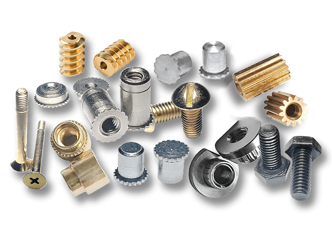
Our Products //
Hot Products
If you are interested in our products, please consult us
Kunshan Hong Yong Sheng Precision Hardware Products Co.,Ltd. All Rights Reserved. Customised Fastener Manufacturer in China
